Mon 28th Jun 2021 - How Does a Stepper Motor Work?
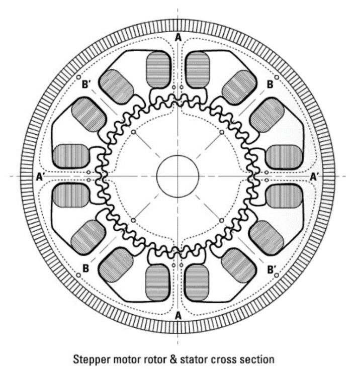
A stepper motor is a simple two phase brushless synchronous motor containing a segmented magnetized rotor and a stator consisting of a prescribed number of electromagnetic coils. When energized, these coils create north and south polls that push or pull the segmented magnetized rotor to make it spin. The illustration shows the internal construction and tooth alignment of a typical hybrid stepper motor. The fine teeth, evenly spaced around the entire diameter, provide the incremental angular rotation that results in mechanical motion.

Stepper motors consist of two windings (2 phase) energized with DC current. When the current in one winding is reversed, the motor shaft moves one step. By reversing the current in each winding, the position and speed of the motor is easily and precisely controlled, which makes the step motor extremely useful for many different motion control applications. The step size is determined by the motor design characteristics, with the 1.8° step angle the most common (consisting of 200 teeth). Other step angles are readily available. The number of steps per revolution is calculated by dividing 360° by the step angle.
Stepper motors are selected by holding torque and corresponding rated current. Holding torque specifies the maximum external torque applied to a motor (energized with its rated current) without causing continuous rotation. At the point the motor begins to rotate, the available torque is often referred to as pullout torque. Pullout torque ratings are represented as values plotted on the motor’s speed/torque curves.
The coils of a stepper motor can be configured in a unipolar or bipolar arrangement. Since simple stepper motor driver electronics can be used to sequence the coils to rotate the motor shaft, unipolar configurations are the easiest to control. A bipolar arrangement requires a more sophisticated driver to properly sequence the windings to control the motor, which also provides additional performance benefits, such as a higher holding torque.

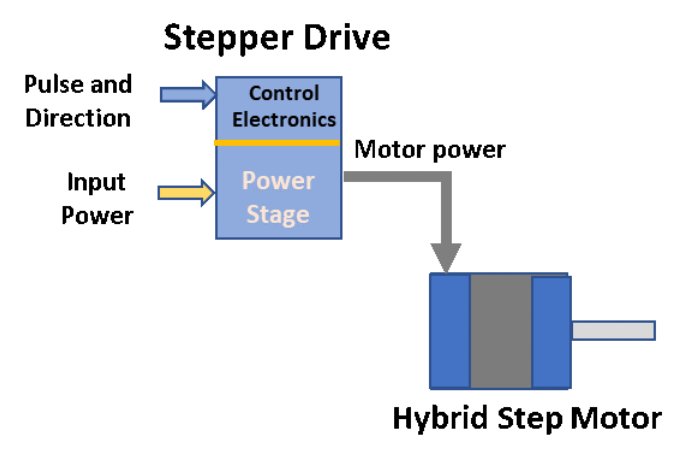
Stepper drives are available in a wide range of voltage and current ratings. A motor’s performance is highly dependent on the current and voltage supplied by the drive. The terms full-step, half-step, and "microstep” are commonly used to discuss step motors. A 1.8° step motor, for example, has 200 discrete positions in a full 360° revolution. Since 360° divided by 200 equals 1.8°, the motor shaft will advance 1.8° each time the motor is commanded to take one step - known as a full-step. The term "half-step” indicates a 0.9° step angle (half of a full 1.8° step) that is achieved by a switching technique that alternately applies positive current, no current, and negative current to each winding in succession. The term "microstep” refers to a more sophisticated form of control that goes beyond the simple switching of power between the motor phase windings to control the amount of current sent to the individual windings. A major benefit of microstepping is to reduce the resonance amplitude that occurs when the motor operates at its natural frequency. Microstepping permits the shaft to be positioned at places other than the 1.8° or 0.9° locations provided by the full-step and half-step methods. Microstepping positions occur between the two angular points in the rotation of the rotor. The most common microstep increments are 1/5, 1/10, 1/16, 1/32, 1/125 and 1/250 of a full step.
This
blog was a collaborative effort among a team of motion and automation experts at Kollmorgen, including engineers, customer service and design experts.
As a Gold Partner, Micromech are able to supply and provide expertise on
Kollmorgen products. Contact our sales team on
01376 333333 or
sales@micromech.co.uk for price and delivery or technical assistance.
Disclaimer
The use of this news article and images came with permission from Kollmorgen.

